Characteristics of Diodes
As shown in the figure, a diode is a component that can allow current to flow only in the direction of ▶. This is a nonlinear relationship in which the forward current \( V_{F} \) rapidly increases when a voltage is applied across the diode above the forward voltage \( V_{F} \). In addition, when the forward current \( I_{F} \) flows, a forward voltage drop \( V_{F} \) must occur.
Since power loss occurs at this time, attention should be paid to component heating in a high-current rectification circuit. When the diode is heated, leakage current increases, and there is a risk of fire due to thermal runaway. Therefore, most diode plastic molds meet the flame retardant standard of UL94V-0 or higher.

Select the Reverse Maximum Voltage \(V_{RM}\) of the bridge diode
In the bridge rectification circuit, while the diode is conducting, the applied voltage \( e\) of each diode terminal voltage \(V_{D}\) becomes \(\sqrt{2}\times e_{rms}\). In reality, if the input voltage of the AC fluctuates, \( e_{rms}\) also changes in proportion to it, so that \(V_{D}\) should not exceed the reverse maximum voltage \(V_{RM}\) of the diode even at the maximum input voltage.
In addition, since the actual rectification circuit has the influence of external noise such as surges, \(V_{RM}\) should be selected sufficiently. In general, a Reverse voltage of twice the rectified voltage is selected, and if the applied voltage is unstable, a higher Reverse voltage selection is required.
Selection of forward current \(I_{F}\) for bridge diode
In a typical rectifying circuit, the current \(i_{c}\) flowing through the diode flows in a pulse waveform rather than a sine wave. This pulse current has a maximum value that changes under various conditions.
First, since the average value \(I_{ave}\) of \(i_{c}\) flowing through the diode must be equal to the DC current \(I_{O}\) after rectification, if the period of half-cycle is \(T\), and the period of current flowing is \(t_{1}\), it becomes \(\frac{1}{T}\int_{0}^{t_{1}}i_{c}dt=I_{0}\).

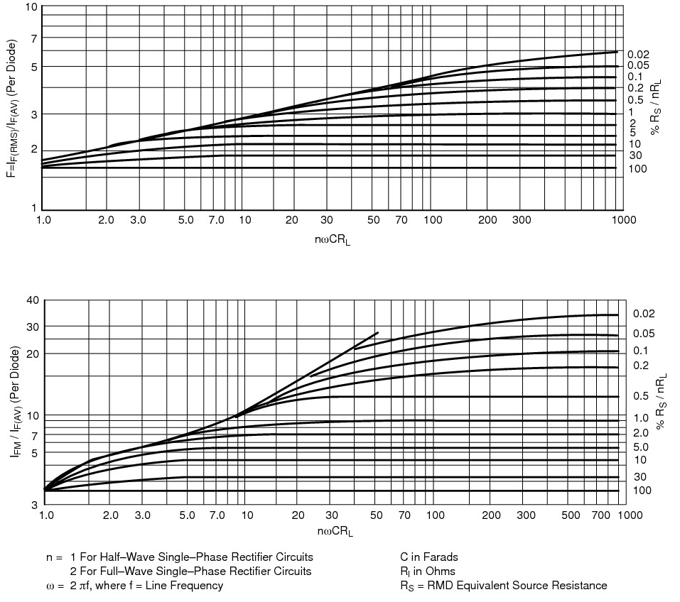
From O.H Schade, Proc. IRE, Vol. 31, 1943, p. 356
In general, the forward current \(I_{F}\) of a rectifying diode is maximum rated from the average value of this \(i_{c}\). However, this is the value when the current flows in direct current, and the pulse current should be considered low in the rated value. The maximum value \(i_{CP}\) of this pulsed current can be obtained from O.H. Schade’s graph. (n\) of \(n\omega CR_{L}\) on the horizontal axis has a coefficient of 0.5 at double voltage rectification, 1 at half-wave rectification, and 2 at full-wave rectification. \(C\) is the capacitor capacity, and \(R_{L}\) is the load resistance value.
Next, \(R_{S}/\left ( nR_{L} \right )\) of the vertical axis means a ratio of the load resistance and the line impedance. The line impedance \(R_{S}\) should be considered to include not only the resistance value of the wiring but also the winding resistance of the power transformer.
Under these conditions, the values of the left vertical axis are read from the graph below. This value multiplied by the output current \(I_{O}\) is the maximum current value \(i_{CP}\).
Selection of diodes considering surge current
Another current condition of the diode is surge current \(I_{FSM}\). In the rectifying circuit, when the power switch is initially operated, the charging voltage of the capacitor is set to 0V. Therefore, at the moment when the switch is operated, a large charging current flows to the capacitor. This is called the inrush current, and the terminal voltage of the capacitor is increased by this large charging current, and accordingly, the current value of the charging gradually becomes a normal state.
In general, the surge current \(I_{FSM}\) of a rectifying diode has a value of about 10 times that of forward current \(I_{F}\). However, this is a guarantee value of one cycle and the value decreases when the temperature of the diode is high.
Power loss of diode
The diode suffers power loss due to the forward voltage drop \(V_{F}\) and the forward current \(I_{F}\). And as a result, it generates heat and increases the temperature. Silicon diodes currently in general must not exceed the maximum junction temperature \(T_{j(max)}\) 150℃. Since the current rating of the diode is determined under the condition of reaching the junction temperature, it is necessary to install a heatsink to lower the temperature when the temperature is high.
It is not easy to calculate the power loss of a diode strictly. The simple calculation method is calculated by multiplying the output current \(I_{O}\) after rectification at the forward voltage drop \(V_{F}\) as the loss. In addition, in a bridge diode, the total loss should be doubled because current always flows through two diodes.